KCFS Seabee Owners Manual
REPUBLIC RC-3 SEABEE · Pilot's Operating Handbook
Overview
The document is the Pilot Operating Handbook (POH) for the Republic RC-3 Seabee, detailing its performance, specifications, and operational procedures. It provides comprehensive instructions for preflight checks, engine operation, and maintenance to ensure safe and efficient flying.
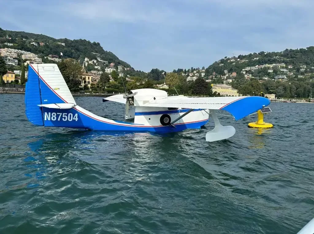
- The Seabee is an amphibious monoplane accommodating a pilot and three passengers.
- Cruising speed at 75% power is 103 mph.
- Take-off distance on land is 800 ft and on water is 1000 ft.
- The aircraft features a spacious cabin with soundproofing and adjustable seats.
- The engine is a Franklin '500' rated at 215 horsepower.
- The maximum gross weight is 3150 lbs.
- The Seabee has a range of 560 miles at cruising speed.
- Preflight checks are essential for safety.
Summary written by AI from the source document. Check the original before relying on it. See which parts of Sprinkle are written by AI.
Reference only, not for flight. Use the current approved manual for your aircraft. See terms, section 5.
Document
Source
Copy found at avsport.org. Sprinkle hosts a reference copy with an added summary, specifications and searchable full text.
Document details
- Type ·
- Pilot's Operating Handbook
- File size ·
- 8.1 MB
- Copy found at ·
- avsport.org
- Language ·
- en
Specifications & performance
Extracted from this document.
Specifications
- Span max (ft) ·
- 37' 8"
- Height max (ft) ·
- 10' 1"
- Length max (ft) ·
- 28' 0"
- Wheel span (ft) ·
- 7' 6"
- Cabin width (ft) ·
- 3' 10"
- Cabin height (ft) ·
- 4' 2"
- Cabin length (ft) ·
- 9' 2"
- Draft loaded (ft) ·
- 1' 6"
- Wing area sq (ft) ·
- 196 sq. ft.
- Baggage volume cubic (ft) ·
- 20 cu. ft.
Performance
- Range miles ·
- 560 miles
- Climb rate (fpm) ·
- 700 fpm
- High speed mph ·
- 120 mph
- Takeoff land (ft) ·
- 800 ft
- Cruise speed mph ·
- 103 mph
- Takeoff water (ft) ·
- 1000 ft
- Landing speed mph ·
- 58 mph
- Landing run land (ft) ·
- 400 ft
- Landing run water (ft) ·
- 700 ft
Weight & balance
- Useful load (lb) ·
- 960 lbs
- Empty weight (lb) ·
- 2190 lbs
- Gross weight (lb) ·
- 3150 lbs
Common. More common than 83% of the aircraft models we track.
Most owners only have the POH. Here's the essential set for the REPUBLIC RC-3 SEABEE.
- Pilot's Operating Handbook / AFM
- Checklist
- Maintenance Manual
- Parts Catalog (IPC)
- Systems & Wiring
- Service Bulletins on file
- Type Certificate (TCDS)
REPUBLIC RC-3 SEABEE for sale now
Free — save the RC-3 to your watchlist and track it in one place.
More REPUBLIC RC-3 SEABEEmanuals & documents
If you fly the REPUBLIC RC-3 SEABEE, you may also be researching these.



In this document
Performance & Specifications
Details the aircraft's performance metrics including speeds, take-off distances, and climb rates.
Operating Your Seabee
Covers operational procedures including preflight checks, engine starting, and landing techniques.
Care and Maintenance
Provides guidelines for the maintenance and servicing of the aircraft.
Engine Controls
Describes the engine control mechanisms and their functions.
Landing Gear
Explains the operation of the landing gear and associated signals.
Safety Precautions
Emphasizes the importance of preflight inspections and weather checks.
Summary written by AI from the source document. Check the original before relying on it. See which parts of Sprinkle are written by AI.
Safety notes
- Complete inspection of the Seabee should be made before each flight.
- Check weather forecasts as they significantly affect flight safety.
- Ensure the ignition switch is in the off position before starting inspections.
- Inspect for cracks and corrosion, especially when operating on salt water.
- Make sure all doors and access openings are properly fastened.
Summary written by AI from the source document. Check the original before relying on it. See which parts of Sprinkle are written by AI.
Full document text
1 2 PERFORMANCE & SPECIFICATIONS.........6 GENERAL......................................................8 OPERATING YOUR SEABEE .......................10 EXTERIOR CHECK (PREFLIGHT) ........11 INTERIOR CHECK (PREFLIGHT)..........12 STARTING ENGINE...............................12 WARM UP ..............................................13 FINAL CHECK ........................................13 LAND TAKE-OFF ...................................14 WATER TAKE-OFF ................................14 CRUISE CONTROL................................15 CLIMBING ..............................................15 STALLING ..............................................15 DIVING ...................................................16 APPROACH ...........................................16 LANDINGS .............................................16 STOPPING ENGINE ..............................17 EMERGENCY OPERATION ..................18 SYSTEMS......................................................21 ENGINE..................................................21 FUEL SYSTEM.......................................22 ENGINE CONTROLS .............................24 SURFACE CONTROLS..........................26 LANDING GEAR.....................................28 HYDRAULIC SYSTEM ...........................30 BRAKES AND WHEELS ........................32 3 CARE AND MAINTENANCE .........................34 ACCESS.................................................34 HANDLING, JACKING, ANCHORING....35 LUBRICATION DIAGRAM......................36 SERVICING DIAGRAM ..........................38 SERVICING THE SHOCK STRUT .........40 REMOVAL OF WHEEL AXLE ................41 TIE-DOWN AND MOORING ..................42 CONTROL SETTINGS ...........................43 UPHOLSTERY .......................................44 EXTERIOR SURFACES.........................44 PLEXIGLASS .........................................44 WHEELS ................................................46 BRAKES .................................................46 BRAKE ADJUSTMENT ..........................47 TAIL WHEEL UPSTOP...........................47 LANDING GEAR SIGNAL SWITCHES...48 CYLINDER ADJUSTMENT ....................48 FUEL FLOW SHUT OFF ........................49 VALVE ADJUSTMENTS.........................49 CARBURETOR ......................................50 ENGINE..................................................51 INSPECTION.................................................52 10-HOUR INSPECTION .........................52 25-HOUR INSPECTION .........................53 50-HOUR INSPECTION .........................56 100-HOUR INSPECTION .......................56 4 5 To you, the new owner of the Seabee, Republic Aviation Corporation is proud to present the product of years of research in amphibian design. Cruising over aerial highways in luxurious comfort, and relaxation, setting down on land or water, the Seabee is the realization of the ideal in personal planes. This sturdy, all metal, amphibious monoplane accommodates a pilot, three passengers, and provides ample space for baggage. The beautifully appointed cabin features sound proofing, draftless ventilation, and a superior lighting system. The cushioned seats are smartly upholstered with plastic coated fabric which renders them water and stain proof. The front seats are adjustable for leg room and may be reclined to form a double bed. Large panels of clear plexiglass afford wide visibility. Generously proportioned doors at each side of the cabin provide easy entry; in addition the Seabee has a wide bow door for fishing and for use at docks and floats. The engine, which is an integral part of the aircraft design, permitting increased efficiency and economy, the practical two way radio, and the wide selection of instruments, coupled with the other outstanding features equip the Seabee for all flights, whether for business or pleasure, at anytime or place. The following pages of this manual contain complete operating instructions, flight checks and service information for keeping the Seabee in perfect condition and are dedicated to the countless carefree flying hours that are to be the pleasure of the Seabee owner. 6 PERFORMANCE (SEA LEVEL) High Speed ............................................................. 120 mph Cruise at 75% power .............................................. 103 mph Landing Speed ......................................................... 58 mph Climb first minute.................................................... 700 fpm Range at cruising (75 gals).................................. 560 miles Take-off (land) ............................................................. 800 ft Take-off (water) ......................................................... 1000 ft Take-off time (water) ................................................. 25 sec Landing run (land)....................................................... 400 ft Landing run (water)..................................................... 700 ft SURFACE MOVEMENTS Rudder right..................................................................... 30°° Rudder left ....................................................................... 30° Ailerons up ...................................................................... 20° Ailerons down ................................................................. 20° Elevators up..................................................................... 28° Elevators down................................................................ 28°° Water rudder right........................................................... 30° Water rudder left ............................................................. 30° Elevator trim tab up, down ............................................. 22° 7 DIMENSIONS Span (max)...................................................................37’ 8” Length (max)................................................................28’ 0”
Show full textShow less
Height (max) ................................................................10’ 1” Wheel span (main gear) ................................................7’ 6” Cabin width (interior) ..................................................3’ 10” Cabin height (interior)...................................................4’ 2” Cabin length (interior)...................................................9’ 2” Baggage compartment (volume) .......................... 20 cu. ft. Draft loaded ...................................................................1’ 6” Wing area .............................................................. 196 sq. ft. Ailerons................................................................ 13.7 sq. ft. Flaps..................................................................... 25.3 sq. ft. Fin......................................................................... 22.8 sq. ft. Rudder.................................................................. 10.5 sq. ft. WEIGHT Gross weight .......................................................... 3150 lbs Empty weight.......................................................... 2190 lbs Useful load................................................................ 960 lbs POWER PLANT Model............................................................. Franklin “500” Rated horsepower.......................................................... 215 8 ENGINE CONTROLS. The engine controls, which consist of throttle, mixture and carburetor heat are push-pull type, designed so that all knobs are forward against the panel for take-off. When the knobs are pulled out, the selections are: closed throttle, mixture in the idle cut-off and carburetor heat “Hot”. When pushed in, selections are open throttle, carburetor heat “Cold” and mixture auto-rich. The intermediate positions of the mixture control select lean mixtures. PROPELLER CONTROL. The standard propeller installation is ground adjustable and non- controllable. The optional installation is controllable by push-pull control on the instrument panel. To select high RPM, push the control against the panel; to select low RPM, pull the control aft. The controllable propeller is also reversible. To reverse propeller: Idle the engine, place normal pitch control in high RPM, and slide the reversing lever control, which is located overhead, to the full aft position. Note: Do not exceed 1750 RPM in reverse! When returning propeller to normal thrust, be certain that the propeller reversing lever is locked in the forward position so that accidental propeller reversal is impossible. SURFACE CONTROLS. Control of surfaces is by conventional wheel-and-post and rudder pedals. To remove the dual control wheel release the locking clip and pull the pin between the wheels. Remove the dual column from its socket and stow in the bracket provided under the right front seat. Replace the pin and secure it with the locking clip. A conventional trim tab lever and indicator is located overhead. LANDING GEAR. To lower or retract the landing gear, lift the gear selector handle and slide it to the desired position; move the pump handle fore and aft with full strokes until the gear reaches the locked position at which time the signal lights will indicate lock. As an added precaution, pump several extra strokes. 9 LANDING FLAPS. To lower or raise the flaps, lift the flap selector handle and place it in the forward or aft position and pump. Partial flap deflection may be had by returning the selector to neutral after pumping flaps to desired position. PARKING. To set the parking brake, push the pedals and pull the control knob marked “Park”. To release the parking brake, return the parking control and depress pedals. SIGNALS. When the gear signal light is green, the landing gear is locked down; if the signal light is red, the landing gear is up. These signals are automatic. MISCELLANEOUS. To adjust the front seats for leg-room, release the lock at the base of the seat and slide the seat to the desired position. The back rests of the front seats may be reclined to form a double bed. All lights are controlled from switches on the instrument panel. The anchor is stowed under the floor in the forward section of the cabin. The baggage compartment access door is above the rear seat. A single fuel pressure gage provides readings for both fuel pumps. To select the desired reading, switch pump selector on the instrument panel to “RIGHT” or “LEFT”. 10 As safety precautions for you as pilot and for your passengers a complete inspection of your Seabee should be made before each flight. Don’t neglect the weather forecasts. Weather conditions play one of the most important parts in successful flight. Check all instructional material for procedures and follow them. Don’t start inspection until ignition switch is checked for off position. 11 EXTERIOR CHECK (PREFLIGHT) Look your airplane over carefully; walk around it and observe the landing gear, floats, water rudder and attachments for looseness or wear. Examine the structure for cracks and for corrosion particularly if you are operating on salt water. Check oil level and view lines and connections for leaks. Be on the lookout for proper safetying of bolts, nuts and turnbuckles. Move control surfaces and note their alignment and soundness. Make certain the doors, access openings, inspection plates and cowlings are properly fastened. Inspect your fueling. Make absolutely certain that the gas cap is properly replaced and firmly secured on the filler neck. Survey the propeller for nicks, cuts and cracks. Drain water at strainer and tank sump drains and check that drain cocks are closed. 12 INTERIOR CHECK (PREFLIGHT) As soon as you enter the cabin require your passengers to fasten their safety belts; then fasten yours. Cultivate this habit. Carefully view the cabin and note that all doors are securely closed and that your fire extinguisher and first aid kit are at hand. Check your surface controls again from the inside---raise and lower the elevators...work the ailerons and rudder...move the engine controls. Check propeller reversing lever for normal thrust setting and insure that the lock is engaged so that the propeller may not be reversed accidentally. With your ignition switch still in the “OFF” position, turn on the battery switch. Observe your lights and instruments. Consult the weight book for permissible loading and check that you are within the load limits; then set trim in proper relation. STARTING ENGINE As a precautionary measure before starting engine always make certain that no one is near the propeller. If the engine has not been operated for some time and is cold, it is a good policy to pull the propeller through by hand for about two revolutions before starting. To start the engine, open throttle slightly beyond the idle position. Push mixture control in to the full rich position and carburetor heat control to the cold position. Close battery switch and place ignition switch to “START” position. When engine fires return ignition switch to “B” (both) position. Do not operate starter for more than 30 seconds at any one time; allow one minute rest before engaging the starter again. If the engine appears to be loaded (flooded), place mixture in the idle-cut-off position (full out), open throttle wide and crank the engine over with the starter to clean out the mixture before attempting to start in the regular manner. 13 WARM UP As soon as the engine fires, check the oil pressure gage; if oil pressure is not indicated within a few seconds after starting, shut off engine at once and investigate the cause. Operation with lack of lubricant can result in severe engine damage. After starting engine set throttle for a speed of about 900 RPM and permit the engine to warm up at this speed for several minutes. Then increase speed to 1200 RPM. After further warm up check engine operation on single magnetos at full throttle. Maximum permissible drop from double to single ignition is 150 RPM. Do not operate on the single magneto for any period of time other than that required to note the RPM drop. If the controllable propeller is installed, check for pitch change and reverse action. First make sure that your doors are securely closed. FINAL CHECK As a last minute check, prior to take-off, see that safety belts are fastened securely. Examine the control panel again and verify that mixture control is in the full rich position. Check for oil pressure and temperature, fuel pressure and generator charge. Check that lock of propeller reversing lever is in the forward position. 14 LAND TAKE-OFF After the ground test has been completed the Seabee is ready for take-off: Taxi airplane forward in order to lock and center tailwheel. Open throttle to full RPM. The airplane will take off in about 800 feet with a normal load; when airborne, retract the landing gear. Adjust throttle to power desired (see power charts). WATER TAKE-OFF Take-off from water presents little difference from normal land take- off except that on water the Seabee requires about 1000 feet of run at sea level, with full gross load and no wind. Extreme care should be exercised on glassy water take-offs. Be sure to continue the climb after leaving the water to prevent the possibility of letting the nose drop and flying back onto the water. Use fully-extended flaps for water take-offs. When airborne, retract the flaps at a slow, steady rate. CAUTION Do not retract flaps at less than 250 feet altitude for airspeeds below 80 mph. 15 CRUISE CONTROL For increased economy in level flight the mixture may be leaned provided that allowable cylinder head temperatures are not exceeded. To lean, maintain constant throttle position in level flight and observe RPM indicator while adjusting mixture control; mixture setting is at best power when RPM is maximum. A change in altitude or throttle setting will necessitate readjustment of the mixture control. Maintain correlated rpm- manifold pressure settings for controllable propeller installations. CLIMBING At sea level the Seabee climbs at a rate of 650 feet per minute. The best climb occurs at 75 IAS and at 2500 RPM with flaps and gear up. STALLING Stalling speed at sea level is 58 IAS with flaps and wheels down and 66 IAS when landing gear and flaps are up. Ample warning of approach to the stall is evidenced by a noticeable buffeting of the control column. When the stall occurs, the Seabee pitches moderately with little tendency to roll, then regains flying speed. A spin will not occur unless assisted by uncoordinated control movements. Should the airplane go into a spin, recovery is accomplished by neutralizing the controls. Recovery may be hastened by using normal recovery technique; namely, rudder against the spin followed by a slight forward movement of the control column. A burst of power greatly accelerates recovery. 16 DIVING CAUTION Do not exceed 159 mph in dives APPROACH Before approaches for landings, place mixture in the “full-in” position (rich) and propeller control to high RPM position. See that all safety belts are fastened and check the fuel quantity. If necessary, set the carburetor to “HOT”. With the throttle set at 1000 RPM, maintain an approach speed of 80 IAS. This speed is best for dead stick landings. LANDINGS CAUTION Before landing check that the mixture selection is full-rich and that propeller control is in high-RPM. For a land plane landing set the selector valve for flaps and gear to 17 the forward position and pump until the signal light glows green signifying that the wheels are down and locked. When close to the runway cut the throttle; with moderate use of the brakes the landing roll will be about 400 feet. After completion of the landing roll raise the flaps and taxi to position desired, then set the parking brake. Normal landing of the Seabee on water involves the same landing technique except that the gear remains up (signal light red) and flaps are down. The airplane hydroplanes on its vee bottom and directional and lateral control is maintained as long as there is forward speed. The water rudder operates in conjunction with the air rudder. When landing the Seabee on glassy or still water, make no attempt to judge height; use night landing technique. Adjust power to maintain 65 IAS with flaps down. This combination will insure a nose-high attitude and gradual rate of descent. Allow the airplane to land itself using a slight amount of back pressure on the control wheel. When the water is contacted, close the throttle and proceed as normal. STOPPING ENGINE Permit the engine to run at approximately 800 RPM for a short time before stopping it. To stop engine pull mixture control lever full out to the idle-cut-off position. After the engines stops, shut off the ignition switch and then the master and battery switches. 18 EMERGENCY OPERATION Too dark to make a safe wheel landing? Forced landing in a short field? It may never be necessary, but should you be in a tight spot, leave your wheels up or retract them if already down and come in for a keel landing. Flight testing proves that an emergency keel landing in the Seabee is apparently a safe landing. The Seabee has been keel-landed on hard surface runways, on sand beaches, and on turf. If, on an approach, you find it necessary to undershoot a field due to running out of gas or engine failure or for other reasons, and have not time to fully retract the landing gear, move the landing gear selector handle back to “landing gear up” position and start pumping. The first couple of strokes will unlock the gear and move it sufficiently aft to permit it to swing on landing. The extent of damage in this event will be slight and most important of all there is negligible danger of personal injury. Remember, in any emergency, a keel landing is the best way out. The Seabee has been demonstrated to be fully maneuverable under all flight conditions with one flap down and the other up. Test stalls and recoveries in this condition experienced no change from normal characteristics. Therefore in the event that one flap only should deflect or if one flap fails to retract, excess aileron is available for use against the extended flap and the Seabee can be flown with relative ease. Negligence in failing to check doors closed before flight, can be the only reason for a bow door swinging open during a negative-airload- creating maneuver; in this condition the Seabee is easily maneuverable and controllable for a perfectly safe landing. Some buffeting will occur due to the interrupted air flow, but it is best to avoid any possibility of this experience by checking your doors closed before take-off. During water operation with one float only, hold that float on the water keeping the other wing out of the water. Effective aileron control can easily be maintained at 40 mph or over. If speed is less, the airplane may be held in its normal attitude by keeping the wing with the missing float headed into the wind so that the airplane will lean over onto the other wing. If the wing without the float has dropped into the water, it may be lifted out of the 19 water by stepping out throwing your weight on the wing lift strut of the opposite wing. You can then taxi to shore. Any water in the wet wing will drain off in a few moments. Don’t forget that Seabee seat backs and cushions are designed to support a person afloat and may be used as life preservers in an emergency. Fuel-flow may be completely cut-off, if necessary, by pulling forward on the fuel flow shut-off control, which is located under the pilot’s seat. Your best assurance against emergencies, is faithful inspection, care and proper maintenance. 21 ENGINE The Seabee is equipped with a Franklin “500” engine which is a six cylinder, 500 cu. in. displacement, direct drive, horizontally opposed engine. The engine is mounted to rigid structure by three shock mounts, two at the front and one at the rear. Detailed specifications are: Rated HP 215 Rated Speed 2500 RPM Idle Speed 500 to 600 RPM Fuel-Min Octane 80 Nonleaded Aviation Compression Ratio 7.0:1 Displacement 500 cu. in. Bore 5 cu. in. Stroke 4.25 Fuel Pump Dual AC Diaphragm Type Carburetor Marvel MA4-5 Ignition Dual Eismann Magneto Model LA-6 Magneto Point Clearance .019”-.021” Ignition Timing 32°° Adv. Left and Right Firing Order 1-4-5-2-3-6 Oil Capacity 13 quarts Oil Temp (Max) 230° F Oil Press (Max) 50 psi Spark Plugs Auto Lite AH4A Spark Plug Gap .014” to .018” Valve clearance .040” (with lifters bled down) Starter 12 volt Generator 12 volt, 35 Amps 22 FUEL SYSTEM Fuel for the Seabee is contained in a plio-cell bag of 75 U.S. gallons capacity located in the hull under the baggage compartment. The fuel is piped to the carburetor through a strainer and pumped by two AC diaphragm type engine driven pumps. Either pump can supply sufficient fuel to the engine. The fuel level quantity gage is electrically operated from a float in the fuel tank. A fuel pressure gage indicates pressure for either the left or right fuel pump as selected by a fuel pump switch on the instrument panel. Normally the fuel is shut off by pulling the mixture control to the idle cut-off position; in emergencies fuel may be stopped by pulling on the fuel-flow shut-off control located under the pilot’s seat. 23 FUEL SYSTEM DIAGRAM 24 ENGINE CONTROLS. The Seabee engine controls are flexible shafts of the push-pull type. Controls are provided for the throttle, mixture, carburetor heat and propeller and are designed so that they are pushed forward against the instrument panel for the take-off condition. The propeller reverse control is directly overhead and is designed so that a positive lock must be disengaged before reversing the propeller. Before reversing propeller make certain that engine is idling and that doors are closed. Maximum RPM in reverse is 1750 RPM. 25 ENGINE CONTROLS DIAGRAM 26 SURFACE CONTROLS The control surfaces of the Seabee are actuated by the rudder pedals and the control wheel through a series of flexible cables housed under the cabin floor and lead through a series of pulleys to the control surfaces. The dual rudder pedals are synchronized with the pilot’s pedals by mating gears on the connecting torque tubes between the two sets of pedals and the dual control wheel is synchronized with the pilot’s wheel by engaging a split sprocket in the dual control column to a mating sprocket in the pilot’s control wheel column. The dual column is removable and may be stowed under the front seat in the bracket provided. The water rudder cables are spliced to the air rudder cables so that operation of both surfaces is synchronized and made by the same pedals. The elevator trim tabs are controlled through sprockets and chains at the control and the surfaces. The control is by crank located overhead of the pilot. Fixed tabs are provided on the aileron and rudder. 27 SURFACE CONTROL DIAGRAM 28 LANDING GEAR The hydraulically controlled landing gear is maintained in the up or down position by the geometry of the linkage. As noted on the landing gear diagram on the facing page, the linkage is designed so as to “break” during the transition phase of the gear operation and to “remake” at the up or down position, so that the center pivots of the linkage are past dead center travel. In this manner, positive lock is maintained until hydraulic pressure is applied to the cylinder permitting a “break” in the linkage. Note that the tail wheel is rotated to the up and down position and that the main gear is retracted and extended. 29 LANDING GEAR DIAGRAM 30 HYDRAULIC SYSTEM The flaps, main landing gear and the tail wheel are extended and retracted hydraulically. A single, manually-operated hydraulic pressure system activates both the landing gear and the flaps. A lever, extending upward from beneath the floor between the two front seats activates the pump with which hydraulic pressure is built up. Two other arms extending from this unit control the action of the fluid. The right lever directs the section of the landing gear while the one located on the left side determines the position of the flaps. The hydraulic power pack incorporates a series of check valves which prevent the temporary dropping off of pressure when transferring the hydraulic action from wheels to flaps or reverse. The system has a three and one-half pint capacity and uses a petroleum oil base hydraulic fluid, Specification 3580D or equivalent. 31 HYDRAULIC DIAGRAM 32 BRAKE AND WHEELS The main wheels of the Seabee 7.00 x 8 and the tail wheel is a 10” smooth contour type. Each main wheel is equipped with bladder-type brake which is fed from its own master brake cylinder at each of the rudder pedals. A brake adjuster and a parking valve are installed in each of the lines between the master brake cylinder and the wheel. The positions of these parking valves are controlled at the instrument panel by a single parking control lever. A control is provided in the cockpit to engage or disengage a tail wheel lock thus permitting the tail wheel to be locked in the centered position or to be unlocked in order to swivel. 33 BRAKE DIAGRAM 34 Access and inspection holes are provided in the cabin floor for servicing cables, hydraulic lines, landing gear and gasoline tank. Additional access holes are provided on the exterior at the boom for servicing the tail wheel shaft and surface control cables. The engine cowling is hood type and opens from the aft end for ready access to the power plant. Drain plugs are provided in the keel and at the aft ends of the floats. 55 GROUND HANDLING The best push points for ground handling are the wing struts. Do not use floats, float struts or empennage for push points. JACKING The base of the oleo and the cross tube will accommodate jacks. To jack the tail wheel, place jack under aft end of keel. HOISTING AND LIFTING Hoisting lugs are available for both the engine and the airplane. Do not lift Seabee by the stabilizer. LEVELING Leveling lugs are provided on the door posts for reference in leveling the Seabee. ANCHORING AND TOWING An anchor cleat is provided at the bow of the airplane. Tow by attaching suitable harness or tow bars at the landing gear. 37 LUBRICATION CHART NOTE: Grease propeller with AN-G-15 every 25 hours or more frequently to assure free blade action. 38 GENERAL SERVICING POINTS 39 GENERAL SERVICING CHART 40 SERVICING THE SHOCK ABSORBER STRUT The following service instructions when followed will result in a rapid and proper servicing of your shock absorber. All references used in this outline pertain to the illustration shown. Instructions are given for both pressure readings and measurements. Before attempting to take an extension measurement the airplane must be vigorously rocked. This is necessary since the gear is equipped with packing and is subject to the usual binding loads. It is also recommended that the gear be inflated to a higher pressure and the air bled to achieve proper extension, rather than try to build up the proper pressure by lifting the entire airplane with air pressure. The fluid level should be checked with the gear in the fully compressed condition before inflation. Before attempting to add to or check the fluid it is absolutely necessary to first bleed off any air that might be present by depressing the air valve. When all air has escaped the valve housing may be removed so that fluid can be added. 1. Depress air valve (A). Allow all air to escape. 2. Rock airplane vigorously. Check dimension (X) for full compression. This should be 2 7/16 inches. 3. Remove air valve body (A) and fill to overflowing with petroleum oil base hydraulic fluid Specification AAF-3580D or equivalent. DO NOT USE ALCOHOL OR CASTOR OIL BASE FLUIDS IN SEABEE STRUTS! 4. Replace and tighten air valve body and with the airplane in the empty weight condition, inflate to approximately 140-150 psi. Rock the airplane vigorously to get a true extension reading at “X”. This should be 6½” ± ¼”. 5. If necessary to obtain this reading, slowly bleed the air valve, rocking the Seabee at intervals until the desired dimension has been reached. 6. Should the gas tanks be full but the airplane otherwise empty inflate to approximately 190-200 psi. Bleed air pressure, rocking airplane at intervals until the “X” dimension is 5” ± ¼”. 7. To service the gear on a jacked-up plane, the strut should be inflated to 53 psi ±± 5 psi. This should indicate full extension of 10 7/16” ± ¼”.