Service Bulletin SB016-0003
LANCAIR EVOLUTION · Service Bulletins
Overview
This service bulletin outlines mandatory inspections and modifications for the Lancair Evolution's main landing gear trunnions due to a discovered crack. It details the inspection process, limitations during operation, and installation of a modification kit to reinforce the trunnions temporarily.
- Mandatory inspections for main landing gear trunnions.
- Crack found in the left trunnion of prototype #001.
- Reinforcement modifications are temporary and limited to 50 hours.
- Limitations include one wheel pivot during taxiing and crosswind landings.
- Thorough preflight inspections of landing gear are required.
- Installation of modification kit PN 434-0014A is necessary.
- Contact Lancair Engineering for further instructions after 50 hours.
- Use dye penetrant for crack detection if available.
Summary written by AI from the source document. Check the original before relying on it. See which parts of Sprinkle are written by AI.
Reference only, not for flight. Use the current approved manual for your aircraft. See terms, section 5.
Document
Source
Copy found at evolutionaircraft.com. Sprinkle hosts a reference copy with an added summary, specifications and searchable full text.
Document details
- Type ·
- Service Bulletins
- Year ·
- 2009
- File size ·
- 1.2 MB
- Copy found at ·
- evolutionaircraft.com
- Language ·
- en
What is the Service Bulletin SB016-0003?
The Service Bulletin SB016-0003 is a service bulletins for the LANCAIR EVOLUTION, dated 2009.
What year was the Service Bulletin SB016-0003 published?
The Service Bulletin SB016-0003 — the LANCAIR EVOLUTION service bulletins on file — is dated 2009.
Common. More common than 73% of the aircraft models we track.
Most owners only have the POH. Here's the essential set for the LANCAIR EVOLUTION.
- Pilot's Operating Handbook / AFM
- Checklist
- Maintenance Manual
- Parts Catalog (IPC)
- Systems & Wiring
- Service Bulletins on file
- Type Certificate (TCDS)
LANCAIR EVOLUTION for sale now
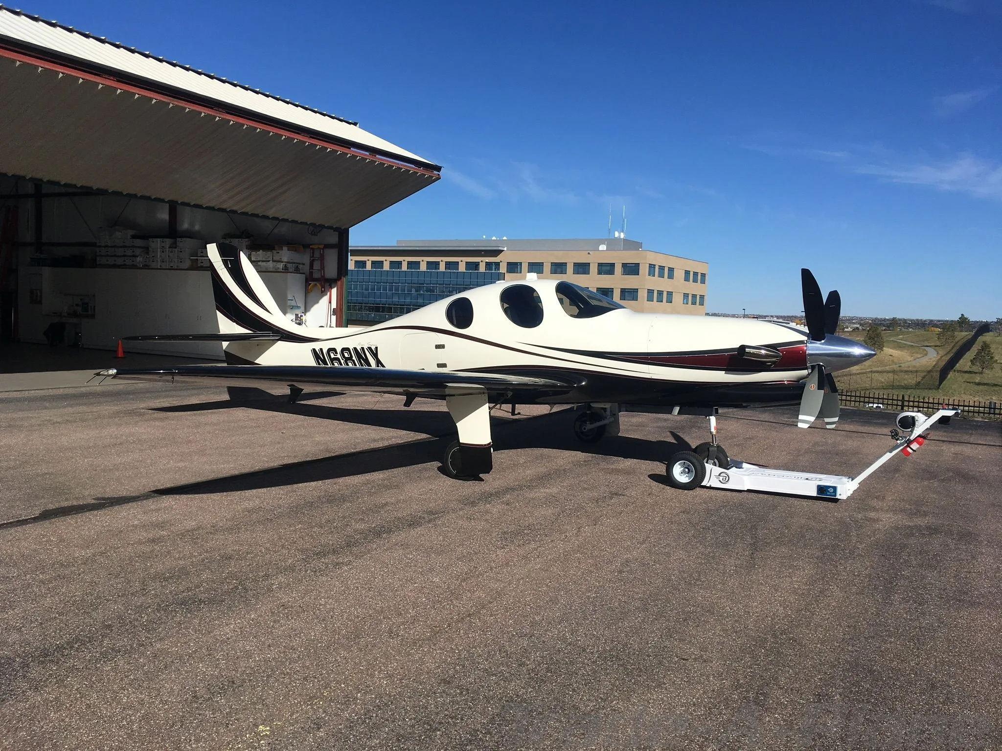

Free — save the EVOLUTION to your watchlist and track it in one place.
More LANCAIR EVOLUTIONmanuals & documents
Related documents
- SERVICE BULLETIN No. 1123CPiper PA-34 Seneca V · Service Bulletins
- Landing Gear Switch Identification and ReplacementLANCAIR EVOLUTION · Service Bulletins
- LANCAIR EVOLUTION Model GuideLANCAIR EVOLUTION · Model Guide
- SERVICE BULLETIN NO. 1377Piper PA-34 Seneca V · Service Bulletins
- SERVICE BULLETIN NO. 1375APIPER PA-32-301FT 6X · Service Bulletins
If you fly the LANCAIR EVOLUTION, you may also be researching these.




In this document
Background
A crack was discovered in the left trunnion of the main landing gear on prototype #001, prompting this service bulletin for inspections and reinforcements.
Action: Phase I
Inspect the entire landing gear for cracks, especially in specified areas, and limit operations as outlined.
Action: Phase II
Install the modification kit PN 434-0014A, which includes specific procedures for bonding and installation.
Action: Phase III
Contact Lancair Engineering after 50 hours for further instructions regarding the trunnions.
Limitations
Operational limitations include one wheel pivot during taxiing and restrictions on crosswind landings.
Installation Instructions
Detailed steps for the installation of the modification kit, including preparation and bonding processes.
Summary written by AI from the source document. Check the original before relying on it. See which parts of Sprinkle are written by AI.
Safety notes
- Remove aircraft from service if cracks are found.
- Limit one wheel pivots during taxiing to a 29-foot minimum turn radius.
- Limit crosswind landings.
- Thoroughly inspect landing gear before each flight.
- Do not touch the bonding surfaces after cleaning.
Summary written by AI from the source document. Check the original before relying on it. See which parts of Sprinkle are written by AI.
Full document text
2244 Airport Way, Redmond, Oregon 97756 Phone 541 923-2233 Fax 541 923-2255 SERVICE BULLETIN SB016-0003 Subject: Evolution Main Landing Gear Trunnion Rev B Date: 12-2-09 Pages:7 Status: Mandatory Inspections, Life limited parts, and Reinforcement Installation Background: A crack was discovered in the “434-0002B Trunnion, Main Gear, Left” on the #001 prototype Evolution. This service bulletin explains how to inspect and reinforce both of the trunnions (434-0002B Trunnion, Main Gear, Left and 434-0003B Trunnion, Main Gear, Right) to detect and prevent cracks. These modifications will be temporary and time limited to 50 hours. After that, Lancair Engineering will advise and/or replace the revision B trunnions. Note: Read and thoroughly understand all instruction before proceeding. If you have questions call Lancair engineering for instructions. Action: Phase I: Inspection & Limitations Inspections: Inspect the entire landing gear, including trunnions and trailing links for cracks, paying special attention to the areas outlined on the attachments #4, #5, and #6. If available, use dye penetrant process to inspect the same areas. If any cracks are found remove aircraft from service and contact Lancair Engineering. Limitations: • Limit one wheel pivots (locking one wheel) during taxiing: 29 foot wing tip minimum turn radius. • Limit cross wind landings. • Every preflight thoroughly visually inspect (flashlight suggested) the entire landing gear with specific attention to the areas shown on attachment sheets #4, #5, and #6. Figure 1 Intact Main Landing Gear Figure 2 Illustration of Cracks in Trunnion Phase II: Installation of Modification Kit PN 434-0014A • Install the eight trunnion boxes PN 230-0008A through 230-0015A following the procedure on attachment #2. • The assembly is shown on attachment #3. The left trunnion assembly is a mirror of the right assembly. • Remove both zerks and progressively drill the threaded zerk holes with .250”, .257”, .261”, .266”, and .277” drill bits. • Ensure all threads are removed without scoring the wall of the cross bolt hole, see attachment #1. • Bond the two 216-0020A Plugs into the drilled zerk holes using the Hysol process stated for closeouts, attachment #2. After installation of trunnion boxes and plugs continue to follow the limitations stated in phase I. Phase III: Replacement Contact Lancair Engineering at 50 hours for further instructions. Page 1 Page 2 Attachment #2 Lancair Landing Gear Closeout Installation 1. Take weight off wheels. 2. Remove trailing links and other attachments on the trunnion that would interfere with closeout installation. 3. Check fit of closeouts and mark bonding surfaces. 4. Clean bonding area with acetone to remove grease and contaminants. 5. Scuff all bonded surfaces with fine emery cloth removing all anodizing. 6. Blow off sanded areas with clean compressed air and do not clean or touch surface. Do not touch the surface with anything. 7. Within minutes of prepping, using properly mixed 9394 QT Hysol Kit, (see can for ratios, mix in one cup then transfer to another cup and mix again) wet out all bonded surfaces with a squeegee. 8. Liberally batter mixed Hysol on bonded surfaces. 9. Insert boxes into trunnions and clamp using soft-face clamps. 10. Scrape up squeeze-out and clean trunnion with acetone. 11. Utilizing heat lamps allow to cure above 75 degrees for over 48 hours. 434-0014A Modification Kit 1ea 230-0008A Closeout, Inboard, Right, Fwd, Landing Gear 1ea 230-0009A Closeout, Inboard, Right, Aft, Landing Gear 1ea 230-0010A Closeout, Outboard, Right, Fwd, Landing Gear 1ea 230-0011A Closeout, Outboard, Right, Aft, Landing Gear 1ea 230-0012A Closeout, Inboard, Left, Fwd, Landing Gear 1ea 230-0013A Closeout, Inboard, Left, Aft, Landing Gear 1ea 230-0014A Closeout, Outboard, Left, Fwd, Landing Gear 1ea 230-0015A Closeout, Outboard, Left, Aft, Landing Gear 2ea 216-0020A Plug, Trunnion, Main Landing Gear 1ea 9394 QT Hysol Kit Page 3 Page 4 Page 5 Page 6 Page 7